Exams/m2014 q6b
From HDLBits
exams/2014_q3cPrevious
Nextexams/m2014_q6c
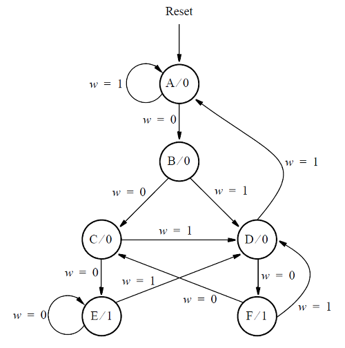
Consider the state machine shown below, which has one input w and one output z.
Assume that you wish to implement the FSM using three flip-flops and state codes y[3:1] = 000, 001, ... , 101 for states A, B, ... , F, respectively. Show a state-assigned table for this FSM. Derive a next-state expression for the flip-flop y[2].
Implement just the next-state logic for y[2]. (This is much more a FSM question than a Verilog coding question. Oh well.)
Module Declaration
module top_module (
    input [3:1] y,
    input w,
    output Y2);
exams/2014_q3cPrevious
Nextexams/m2014_q6c
