Wire4
From HDLBits
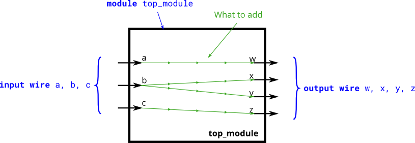
Create a module with 3 inputs and 4 outputs that behaves like wires that makes these connections:
a -> w
b -> x
b -> y
c -> z
The diagram below illustrates how each part of the circuit corresponds to each bit of Verilog code. From outside the module, there are three input ports and four output ports.
When you have multiple assign statements, the order in which they appear in the code does not matter. Unlike a programming language, assign statements ("continuous assignments") describe connections between things, not the action of copying a value from one thing to another.
One potential source of confusion that should perhaps be clarified now: The green arrows here represent
connections between wires, but are not wires in themselves. The module itself already has 7 wires declared (named a, b, c, w, x, y, and z). This is because input and output declarations
actually declare a wire unless otherwise specified. Writing input wire a is the same as input a. Thus, the assign statements are not creating wires, they are creating the connections between
the 7 wires that already exist.

Expected solution length: Around 4 lines.
Module Declaration
module top_module(
    input a,b,c,
    output w,x,y,z );