Exams/2014 q3fsm
From HDLBits
exams/ece241_2014_q5bPrevious
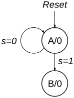
Consider a finite state machine with inputs s and w. Assume that the FSM begins in a reset state called A, as depicted below. The FSM remains in state A as long as s = 0, and it moves to state B when s = 1. Once in state B the FSM examines the value of the input w in the next three clock cycles. If w = 1 in exactly two of these clock cycles, then the FSM has to set an output z to 1 in the following clock cycle. Otherwise z has to be 0. The FSM continues checking w for the next three clock cycles, and so on. The timing diagram below illustrates the required values of z for different values of w.
Use as few states as possible. Note that the s input is used only in state A, so you need to consider just the w input.
Module Declaration
module top_module (
    input clk,
    input reset,   // Synchronous reset
    input s,
    input w,
    output z
);
exams/ece241_2014_q5bPrevious
